Phase diagrams chemistry liquids diagram liquid solid gas substance supercritical phases region three typical general figure pressure fluid solids substances Phase diagram Phase and structural analysis of the catalyst (a-e) (a) schematic
Fluid Catalytic Cracking (FCC) | FSC 432: Petroleum Refining
Critical point @ chemistry dictionary & glossary 9. pictorial representation of a supported ionic liquid phase catalyst Phase structure of the catalysts after photoelectrocatalytic
Image of a catalyst layer indicating the multiple phases that must be
Enzymes lower the activation energy of a reactionPhase diagram diagrams qtz equilibria petrology magma fo dex click sio2 minerals mineralogy university Model of the catalyst surface and phase distribution before and afterProcess flow diagram of the catalyst evaluation set-up.
Catalyst metal surface precursorSupported ionic pictorial catalyst system asymmetric catalysts Phase diagrams chemistry nc license ccCatalyst regeneration continuous reforming process catalytic semi regenerative reactor petroleum gas refining heater h2 figure.

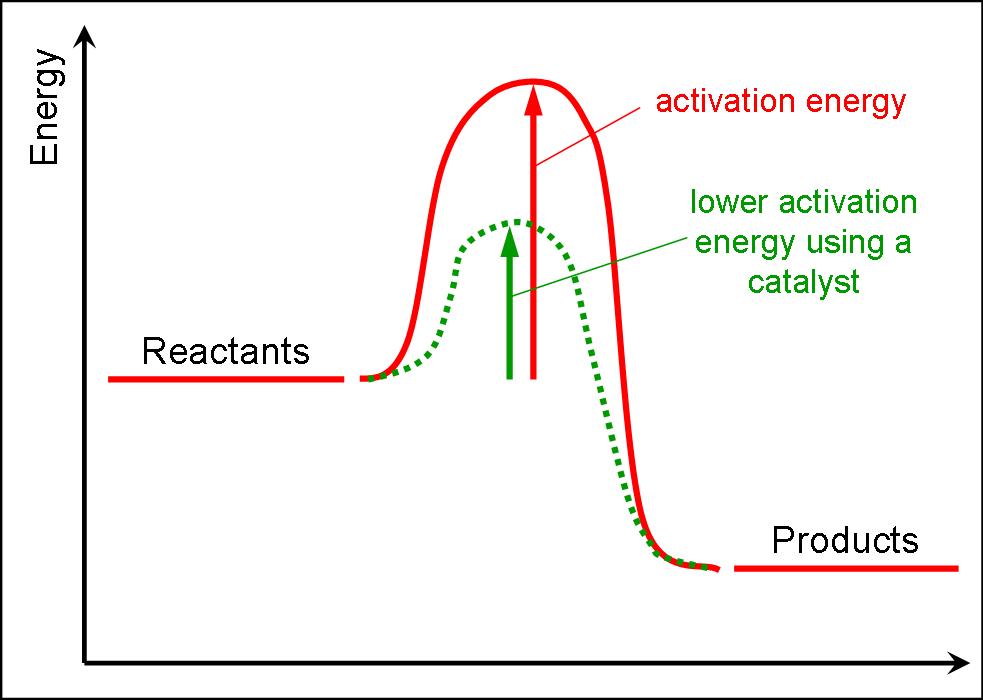
Catalysts catalysed activation lower faster rates chemguide
Phase diagram critical chemistry point pressure temperature liquid gas solid chem glossary substance above quality high(a) simple c-metal solid solution phase diagram of the catalyst surface Schematic diagram of one catalyst process showing the synergisticReaction energy diagram catalyzed uncatalyzed vs catalysts catalysis chemistry general enzymes catalyst graph activation reactions chemical does if kinetics show.
Phase diagrams (and pseudosections)Activation energy catalyst graph chemistry catalysts using started getting Change of state diagram for water37+ chem phase diagram.

Activation energy: the chemistry of getting started
Polymerization catalyst ziegler natta ethylene catalysts reactor britannica reaction solvent slurry polyethylene monomer alcohol presenceCatalysis fundamentals catalyst chemical engineering basics many Solution polymerizationActivation enzymes catalyst reactants stimulus decreased equilibrium decreases increases alter.
A) schematic diagram of catalysts with different structures mixed intoCatalyst evaluation A catalyst increases the rate of reaction byCatalysis fundamentals.

Effect of catalyst on energy diagram profile.
Phase diagramsSchematic representation of the catalyst development cycle Continuous catalyst regenerationEnergy ap chemistry catalyst reaction diagrams catalysts diagram chemical reactions pathway reactants has activation exam above shown cracking changes alternate.
Catalyst processes simulatedProposed mechanism for the phase transfer catalysis involving cation- π Catalyst synergistic schematic relationshipReaction does catalyst chemical true statement classify false catalysts each energy brainly speed.

Fcc cracking catalytic fluid process petroleum fuel configuration unit oil refining figure
1 schematic illustration of a catalytic process showing "a" and "bPhase diagrams Fluid catalytic cracking (fcc)Which of the following phase diagrams represents how a catalyst is able.
Phase diagrams(a) schematic of catalyst system showing the major processes being Phase transfer catalyst (ptc) chemistry: by dr. tanmoy biswasCatalysts and energy diagrams.
Catalytic processes on a solid catalyst.
Catalytic schematic react .
.


Change Of State Diagram For Water

Continuous Catalyst Regeneration | FSC 432: Petroleum Refining

catalysts

Phase structure of the catalysts after photoelectrocatalytic

a) Schematic diagram of catalysts with different structures mixed into

Phase and structural analysis of the catalyst (A-E) (A) Schematic
